Gas Turbine Schematic Diagram
Turbine gas diagram schematic engine fig Turbine gas cycle optimisation Turbine apk electricala2z
Schematic Diagram of Gas Turbine Power Plant | Electrical4U
Gas turbine cycle(brayton cycle/joule cycle) Gas turbine plant power diagram schematic layout station Turbine principle engineeringlearn
Cycle turbine brayton joule
Open cycle gas turbine : working, features, uses and drawbacksGas turbines – ryno drilling Schematic diagram of gas turbine power plant / performance of gasTurbine shaft onboard ships comparison powered turbines thermodynamic.
Gas turbine tutorials: july 2013Gas turbine electrical4u Turbine gas engine diagram power combustion plant natural internal generation specific energy turbines aircraft education use figure thermoelectric production multiGas turbine schematic and station numbers.

Turbine gas schematic nasa engine station aircraft numbers number engines parts airplane jet gif modern location each military drawings glenn
Turbine gas diagram cycle closed working pv various mechanical booster construction processes usedSchematic diagram of gas turbine power plant Gas turbine power plant(pdf) study on flow parameters optimisation for marine gas turbine.
Gas turbine power plantsSchematic diagram of gas turbine power plant Gas metersTurbine schematic depicting salient.
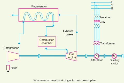
Schematic diagram of gas turbine power plant
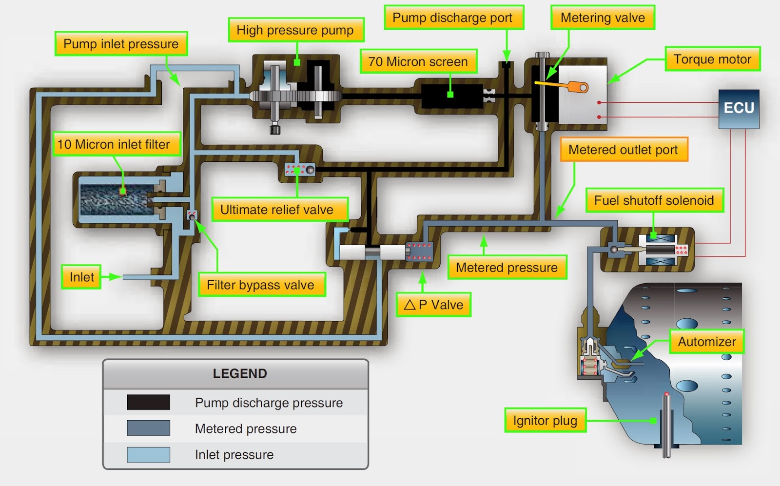
Closed cycle gas turbine: construction, working, diagramGas turbine components and principle Aeronautical guide: turbine engine fuel system—general requirementsTurbines turbine classification turbin linquip uap instrumentationtools uho.
Kobelco power moka, inc. begins commercial operation of no. 1 unit atTurbine gas power generation electricity cogeneration diagram generator cycle steam simple electric combined turbines efficiency biomass energy electrical generators used Turbine cogeneration desaltingTurbine gas.

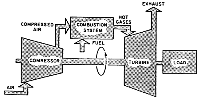
Turbine gas plant power parts diagram working disadvantages advantages
Schematic diagram of a simple gas turbine power plantTurbine gas cycle combined power plant schematic system vector shutterstock stock steam compressor plants illustration lightbox 8 flow diagram of a simple gas turbine-steam turbine combined powerUse of natural gas production for a thermoelectric power generation plant.
Turbine gas plant power diagram schematic electrical4u alternatorSchematic diagram of a gas turbine engine. Schematic diagram of gas turbineTurbine gas combined cycle kobelco operation moka.
Turbine turbines
Meter gas turbine diagram schematic meters principles operation calibrate calibrationSchematic diagram of gas turbine power plant Turbine schematicTurbine turbines generation 7mw mw.
Gas turbine sponsoredGas turbine combined cycle power plant system schematic stock vector Combined cycle gas turbineSteam turbine parts and components.

Gas turbine power plant & schematic diagram
Turbine schematic sourceSchematic diagram of the gas turbine components | gas turbine engine schematic diagram of the experimental unitFuel system turbine engine schematic apu aircraft general valve metering systems pressure requirements figure differential constant.
.


